Blogger Themes

Search This Blog

www.embeddedstudy.com | Copyright © 2017 | All Rights Reserved | Nithin Pradeep . Theme images by Storman. Powered by Blogger.

Popular KOZHI

Sponsor

Download

Blogger Tricks

FEATURED

What is an Embedded System?

An embedded system is a combination of hardware and software that is designed to carry out a certain task or tasks, meaning it has a s...

JOIN THE TEAM

Popular Posts

Wikipedia

Search results

Search This Blog

Social

More Links

Social

ad

ads

Wednesday, 13 September 2017

IoT Based Smart Irrigation Project on Raspberry Pi

- No comments


Hello all...
In this project I am going to discuss ,how to build a Smart irrigation Project using Raspberry Pi


Smart Irrigation system essentially means to measure the water content in the soil continuously and with the help of  a Soil Moisture sensor,

(The Soil Moisture Sensor is used to measure the volumetric water content of soil. This makes it ideal for performing experiments in courses such as soil science, agricultural science, environmental science, horticulture, botany, and biology.)

This Project has 2 modes Automatic as well as manual,In Automatic mode after comparing with a threshold if the soil moisture is less ,it will turn ON a solenoid valve,for watering and vice versa.In Manual mode the user has the right to turn ON/OFF voluntarily.Semaphores concept in Linux OS is used in this project in order to avoid the overlapping of Manual and Auto modes .In this project i have also maintained a log file to monitor the activity of my project.(Time of ON/OFF,Status and the Mode).The time and date fetched using ctime() function .A solenoid valve is also connected in order to control the flow of water.All these components are connected to a Raspberry pi .

This is how the log looks like,


Use the Soil Moisture Sensor to:

 • Measure the loss of moisture over time due to evaporation and plant uptake.
 • Evaluate optimum soil moisture contents for various species of plants.
 • Monitor soil moisture content to control irrigation in greenhouses.
 • Enhance your Bottle Biology experiments.


 How to use the Soil Moisture Sensor

 The prongs should be oriented horizontally, but rotated onto their side – like a knife poised to cut food – so that water does not pool on the flat surface of the prongs. The horizontal orientation of the sensor ensures the measurement is made at a particular soil depth. The entire sensor can be placed vertically, but because soil moisture often varies by depth, this is not usually the desired orientation. To position the sensor, use a thin implement such as a trenching shovel to make a pilot hole in the soil. Place the sensor into the hole, making sure the entire length of the sensor is covered. Press down on the soil along either side of the sensor with your fingers. Continue to compact the soil around the sensor by pressing down on the soil with your fingers until you have made at least five passes along the sensor. This step is important, as the soil adjacent to the sensor surface has the strongest influence on the sensor reading. 


CHECK OUT MY REVIEW ABOUT THE SOIL MOISTURE SENSOR 


 You will get every products at cheap rate at our store, check the link below:
http://www.embeddedstudy.com/p/shop-gadgets.html


Components Required

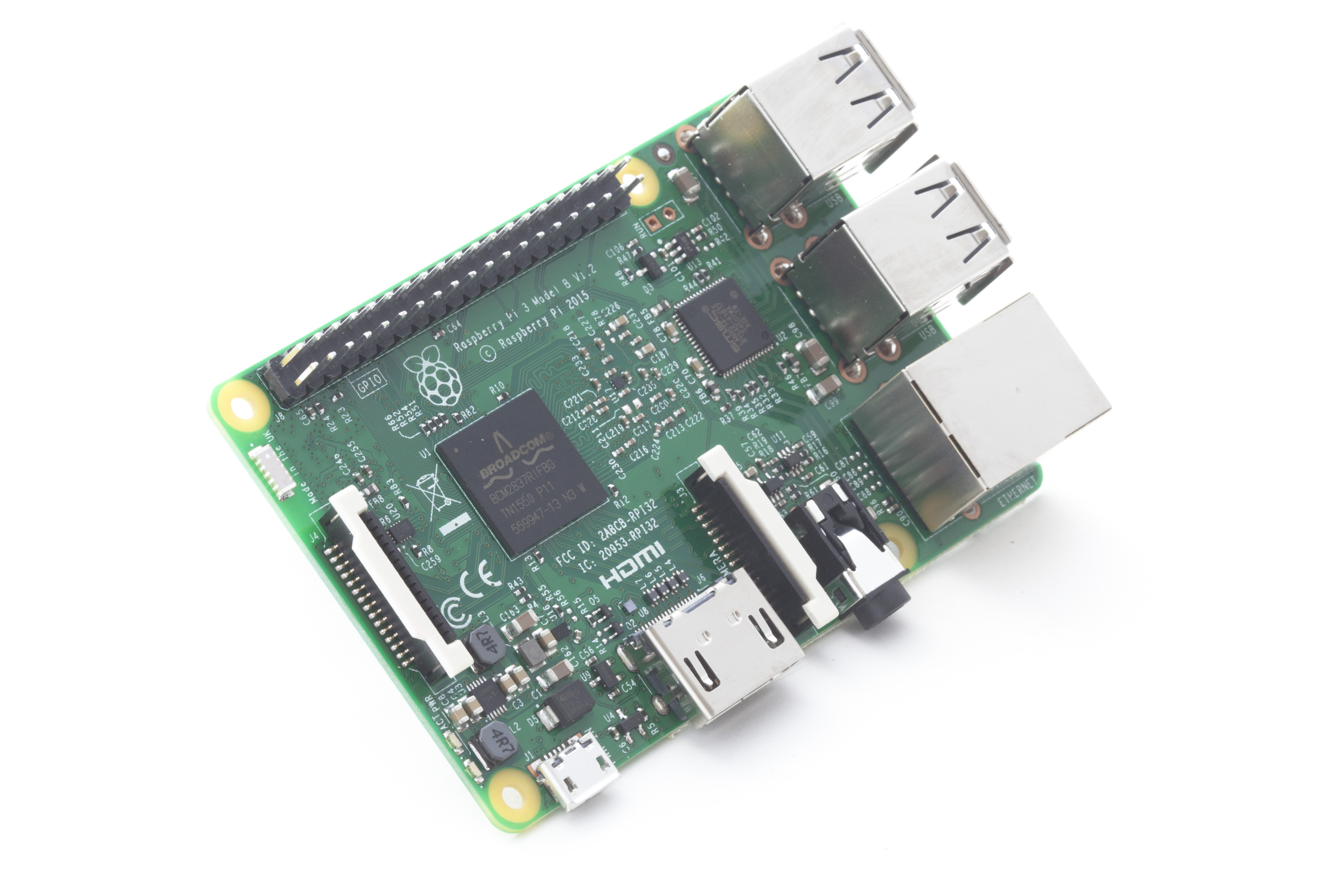
  1. Raspberry Pi 3

The Raspberry Pi 3 is the third-generation Raspberry Pi. It replaced the Raspberry Pi 2 Model B in February 2016. Quad Core 1.2GHz Broadcom BCM2837 64bit CPU. 1GB RAM. BCM43438 wireless LAN and Bluetooth Low Energy (BLE) on board.

2.Soil Sensor Module

I used a 86062 humidity and soil moisture sensor.Controlling the potentiometer we can adjust the sensitivity of the sensor .it has also got led indications over it.


3.JUMPER WIRES

We require Male-Female and Female-Female Jumper wires for connection.

4.MCP 3204(ADC)

MCP3204/3208 devices are successive approximation 12-bit Analog- to-Digital (A/D) Converters with on-board sample and hold circuitry. ... Differential Nonlinearity (DNL) is speci- fied at ±1 LSB, while Integral Nonlinearity (INL) is offered in ±1LSB (MCP3204/3208-B) and ±2LSB (MCP3204/3208-C) versions.


We have already said how to set up the Raspberry Pi and create the pubnub accountin the IoT Based Smart Home on Raspberry Pi
if you have missed that go through it.

CONNECTION DIAGRAM:

check pinout.xyz for Raspberry Pi pins,All pins mentioned here are WiringPi pins.
Connect everything as follows:


PROJECT CODE SNIPPET:

The Project Code is divided in to 2 files you need to make another file other than listen.c  ie adc.h for adc interfacing to soil sensor(I use MCP 3204 ADC) this is for getting precise analog sensor values.

So first create adc.h and include it in the listen.c file.
you can also download whole code zip files
DOWNLOAD 

here is the adc.h file code
#include<stdint.h>
#include<wiringPiSPI.h>

float mcp3204_read(int ch_num)
{

uint8_t buff[3];
int adc;
float vol=0;
if((ch_num>3)||(ch_num<0))
 return -1;

buff[0]=0x06;
buff[1]=ch_num<<6;
buff[2]=0;

wiringPiSPIDataRW(0,buff,3);
adc=((buff[1]&0x0f)<<8)+buff[2];

//printf("%d adc val\n,",adc);
vol=((float)adc*5)/4096;
return vol;
}

code explanation

mcp 3204 uses spi protocol to communicate with Raspberri Pi,mcp3204_read()returns float values of measured moisture.


listen.h file code
#include <stdlib.h>
#include <stdio.h>
#include <string.h>
#include <unistd.h>
#include<wiringPi.h>
#include"adc.h"

#include<sys/sem.h>
#include<sys/ipc.h>
#include<sys/types.h>

#include <json.h>

#include "pubnub.h"
#include "pubnub-sync.h"

#define PUBLISH_KEY "pub-c-c30824bb-bc31-463b-a395-XXXXXXXXXXXX"
#define SUBSCRIBE_KEY "sub-c-cfa511de-660a-11e7-b272-XXXXXXXXXXXX"     //use your Publish and Subscribe keys 
#define IR 1
#define LED 2
#define CHAN 0
#define LED1 25

struct pubnub_sync *_sync;
struct pubnub *p;
json_object *msg;
char *buff;

int flag=0;

char * readPubnub ()
{
 /* Subscribe */
/* 1 */  const char *channels[] = { "ch1", "ch2" };
/* 2 */  pubnub_subscribe_multi(
    /* struct pubnub */ p,
    /* list of channels */ channels,
    /* number of listed channels */ 2,
    /* default timeout */ -1,
    /* callback; sync needs NULL! */ NULL,
    /* callback data */ NULL);
  if (pubnub_sync_last_result(_sync) != PNR_OK)
   return EXIT_FAILURE;
  msg = pubnub_sync_last_response(_sync);
  if (json_object_array_length(msg) == 0) {
   printf("pubnub subscribe ok, no news\n");
  } else {
   char **msg_channels = pubnub_sync_last_channels(_sync);
   
   for (int i = 0; i < json_object_array_length(msg); i++) {
    json_object *msg1 = json_object_array_get_idx(msg, i);
     if(strcmp(channels[i],msg_channels[i])==0)
      printf("%s\n",msg_channels[i]);
     else
      printf("%s\n",msg_channels[i]);
    printf("pubnub subscribe [%s]: %s\n", msg_channels[i], buff = (char *)json_object_get_string(msg1));

   }
  }
  return buff;
        
}


void PubNubInit ()
{
        _sync = pubnub_sync_init();

        p = pubnub_init(
                        /* publish_key */ PUBLISH_KEY,
                        /* subscribe_key */ SUBSCRIBE_KEY,
                        /* pubnub_callbacks */ &pubnub_sync_callbacks,
                        /* pubnub_callbacks data */ _sync);

}

void main(void)
{
 char *on="MOTOR ON";
 char *off="MOTOR OFF";
 FILE *fp;
 
 wiringPiSetup();
 pinMode(LED,OUTPUT);
 digitalWrite(LED,LOW);
 fp=fopen("log","a+");
 
 if(fp<0)
 {
 perror("fopen");
 
 }
 fprintf(fp,"%s\t%s\t\t%s\n","Mode","Status","Time");
 fclose(fp); 
 
 
 struct sembuf v;

 char *readbuff;
 int id=semget(5,1,IPC_CREAT|0644);
 if(id<0)
 {
  perror("semget");
  return;
 }
 semctl(id,0,SETVAL,0);
 time_t t1;
 

 if(fork()==0)
 {
  //manual code
  float f;
  PubNubInit ();
  v.sem_num=0;
  v.sem_op=0;
  v.sem_flg=0;
  if(wiringPiSPISetup(0,1000000)<0)
   printf("no\n");
  else
   printf("done");

  while(1){
   readbuff = readPubnub (); 
   printf ("readbuff = %s\n",readbuff);


   if(strstr(readbuff,"MOTOR ON"))
   {

    f=mcp3204_read(CHAN);
    printf("Manual :%f\n",f);

    semop(id,&v,1);

    if(f>3.8)
    {
     fp=fopen("log","a+");
     semctl(id,0,SETVAL,1); 
     digitalWrite(LED,LOW);//low moisture on the motor
     printf("Manual On \n");
     t1=time(0);
     fprintf(fp,"%s\t%s \t %s \n","Manu:  ",on,ctime(&t1));
     
     fclose(fp);
    }
    else 
    {
     printf("no need\n");  
    }
   }  

   else if(strstr(readbuff,"MOTOR OFF"))
   {
    fp=fopen("log","a+");
    t1=time(0);
    fprintf(fp,"%s\t%s\t %s \n","Manu:  ",off,ctime(&t1));

    digitalWrite(LED,HIGH);
    printf("Manual off\n");
    sleep(5); 
    fclose(fp);
    semctl(id,0,SETVAL,0);
   }
  }

 } 

 else
 {

  float f;
  if(wiringPiSPISetup(0,1000000)<0)
   printf("ADC Enabled in auto mode \n");

  struct sembuf v;
  v.sem_num=0;
  v.sem_op=0;
  v.sem_flg=0;


  while(1)
  {
   f=mcp3204_read(CHAN);
   printf("Auto mode detection :: voltage level : %f\n",f);
   delay(2000);
    
   
   semop(id,&v,1);

   if(f>3.8)
   {
    fp=fopen("log","a+");
    t1=time(0);
    fprintf(fp,"%s\t%s\t %s \n","Auto:  ",on,ctime(&t1));
     
    semctl(id,0,SETVAL,1);
    digitalWrite(LED,LOW);
    printf("Automatic mode motor is switching on fr 40 sec\n");
 
    delay(40000);

    digitalWrite(LED,HIGH);

    t1=time(0);
    fprintf(fp,"%s\t%s\t %s \n","Auto:  ",off,ctime(&t1));
    fclose(fp);

    printf("Auto mode is switching off\n");
    semctl(id,0,SETVAL,0);
   }
   else
   ;

  }

 }
}

//end of main

Read Pubnub,Write Pubnub ,Pubnub Init and declarations are explained in the smart home project (it is almost same..go through it...),so we are only discussing about the main() code.
#include"adc.h"

#include<sys/sem.h>
#include<sys/ipc.h>
#include<sys/types.h>
are added additionally for adc and semaphore operations
#define LED 2
#define CHAN 0
#define LED1 25

Main Function

        char *on="MOTOR ON";
 char *off="MOTOR OFF";
 FILE *fp;
 
 wiringPiSetup();
 pinMode(LED,OUTPUT);
 digitalWrite(LED,LOW);
 fp=fopen("log","a+");
 
 if(fp<0)
 {
 perror("fopen");
 
 }
 fprintf(fp,"%s\t%s\t\t%s\n","Mode","Status","Time");
 fclose(fp);
Declaring 2 strings one for Motor ON and one for OFF,Declaring a file pointer for log
Declaring LED pin and definig it as output(wiring pi pin 2).check pinout.xyz
Writing MODE Status and Time to Log file.


struct sembuf v;

 char *readbuff;
 int id=semget(5,1,IPC_CREAT|0644);
 if(id<0)
 {
  perror("semget");
  return;
 }
 semctl(id,0,SETVAL,0);
 time_t t1;
 

 if(fork()==0)
 {
  //manual code
  float f;
  PubNubInit ();
  v.sem_num=0;
  v.sem_op=0;
  v.sem_flg=0;
  if(wiringPiSPISetup(0,1000000)<0)
   printf("no\n");
  else
   printf("done");

  while(1){
   readbuff = readPubnub (); 
   printf ("readbuff = %s\n",readbuff);


   if(strstr(readbuff,"MOTOR ON"))
   {

    f=mcp3204_read(CHAN);
    printf("Manual :%f\n",f);

    semop(id,&v,1);

    if(f>3.8)
    {
     fp=fopen("log","a+");
     semctl(id,0,SETVAL,1); 
     digitalWrite(LED,LOW);//low moisture on the motor
     printf("Manual On \n");
     t1=time(0);
     fprintf(fp,"%s\t%s \t %s \n","Manu:  ",on,ctime(&t1));
     
     fclose(fp);
    }
    else 
    {
     printf("no need\n");  
    }
   }  

   else if(strstr(readbuff,"MOTOR OFF"))
   {
    fp=fopen("log","a+");
    t1=time(0);
    fprintf(fp,"%s\t%s\t %s \n","Manu:  ",off,ctime(&t1));

    digitalWrite(LED,HIGH);
    printf("Manual off\n");
    sleep(5); 
    fclose(fp);
    semctl(id,0,SETVAL,0);
   }
  }

 } 
Creating semaphore for resource locking and forking child to create MANUAL mode.
if(strstr(readbuff,"MOTOR ON"))
Comparing the string sent from Pubnub with "MOTOR ON",then moisture value is read from ADC to a float variable 'f' ,and if  value is greater than a threshold resource is locked (Auto can't access) LED gets ON ,and will print status to log file ,afterwards close the file that is opened in the append mode,In the else part if there is enough water content no action is taken and will print NO Need....Same for MOTOR OFF also LED gets off and will print the status  to log file..the resource is released only after Motor is OFF and is made available to AUTO Mode..(Resource here means the Status of Pi's pin connected to Solenoid valve).

else
 {

  float f;
  if(wiringPiSPISetup(0,1000000)<0)
   printf("ADC Enabled in auto mode \n");

  struct sembuf v;
  v.sem_num=0;
  v.sem_op=0;
  v.sem_flg=0;


  while(1)
  {
   f=mcp3204_read(CHAN);
   printf("Auto mode detection :: voltage level : %f\n",f);
   delay(2000);
    
   
   semop(id,&v,1);

   if(f>3.8)
   {
    fp=fopen("log","a+");
    t1=time(0);
    fprintf(fp,"%s\t%s\t %s \n","Auto:  ",on,ctime(&t1));
     
    semctl(id,0,SETVAL,1);
    digitalWrite(LED,LOW);
    printf("Automatic mode motor is switching on fr 40 sec\n");
 
    delay(40000);

    digitalWrite(LED,HIGH);

    t1=time(0);
    fprintf(fp,"%s\t%s\t %s \n","Auto:  ",off,ctime(&t1));
    fclose(fp);

    printf("Auto mode is switching off\n");
    semctl(id,0,SETVAL,0);
   }
   else
   ;

  }

 }
}
AUTO mode is written inside the Parent Code.Parent process has all time control and need to monitor the status every time.
Here also while running in the AUTO mode, MANUAL mode must not interfere so we are locking the resource using semaphores.As in Manual mode here also LED status and LOG file entry is changes.In else code we will do nothing.In Auto mode motor is pre-setted to switch On for 40 sec & then turned OFF.

Thats all for this project,Hope you all liked it... Enjoy....

Sunday, 10 September 2017

Make ARDUINO PIANO and play Happy Birthday to you..

- No comments

Hello all in this post i will show you how to make an arduino piano and play your first song in it.
Components needed

HOW TO SET UP THE HARDWARE :
the piano keys...
The piano keypad switches were connected using jumper wires.The main sketch defines which music note frequencies are associated with each piano key.  For this project, I used C4, D4, E4, F4, G4, A4,B4,C5, D5, E5, F5, G5, A5, & B5 with C4 being switch '0', D4 being switch '1'  and so on...  Change the frequency values, or add additional switches to fully customize your own project!
the SPEAKER..


To integrate the Speaker, simply connect one end to the Arduino pin 11, and the other side to ground . The "tone" function in the code will look for this pin in order to play the note called.


  1. Arduino UNO -1
  2. Male to Male jumper wires -10
  3. 4x4 Keypad -1
  4. 4ohm Speakers - 1
  5. A PC or Laptop
Connect the circuit as shown in the diagram

HOW THE CODE WORKS

  • The sketch begins by importing the "Keypad.h" and "pitches.h" libraries so we can reference various items from them later on in the code
  • Next, the code is set up by defining the number of ROWS and COLUMNS determining which pins are inputs vs. outputs, and setting the SPEAKER pin as 11th pin of ARDUINO.
  • Next we define the value of each keys in MATRIX form and assign which pin we need to connect the rows and columns(In this project i have used 3,2,8,0 pins as ROWS and 7,6,5,4 as columns).
the main loop...
  • We are storing each key value to 'customkey' variable and also printing the value in the serial monitor of ARDUINO IDE.
  • Next ,we are comparing each custom key and sending SPEAKER pin NOTE and DURATION to the tone function.


DOWNLOAD SOURCE CODE FILE HERE

Or copy the code below:
/* @file CustomKeypad.pde
|| @version 1.0
|| @author Alexander Brevig
|| @contact alexanderbrevig@gmail.com
||
|| @description
|| | Demonstrates changing the keypad size and key values.
|| #

*/


#include <Keypad.h>
#include "pitches.h"
#define GND 12
const byte ROWS = 4; //four rows
const byte COLS = 4; //four columns
const int SPEAKER=11;


//define the cymbols on the buttons of the keypads
char hexaKeys[ROWS][COLS] = {
  {'0','1','2','3'},
  {'4','5','6','7'},
  {'8','9','A','B'},
  {'C','D','E','F'}
};
byte rowPins[ROWS] = {3, 2, 8, 0}; //connect to the row pinouts of the keypad
byte colPins[COLS] = {7, 6, 5, 4}; //connect to the column pinouts of the keypad

//initialize an instance of class NewKeypad
Keypad customKeypad = Keypad( makeKeymap(hexaKeys), rowPins, colPins, ROWS, COLS); 

void setup(){
  Serial.begin(9600);
  pinMode(GND,OUTPUT);
  digitalWrite(GND,LOW);
}
  
void loop(){
  char customKey = customKeypad.getKey();
  
  if (customKey=='0'){
    Serial.println(customKey);
    tone(SPEAKER,NOTE_C4,350);
  }
  if (customKey=='1'){
    Serial.println(customKey);
    tone(SPEAKER,NOTE_D4,350);
  }
  if (customKey=='2'){
    Serial.println(customKey);
    tone(SPEAKER,NOTE_E4,350);
  }
  if (customKey=='3'){
    Serial.println(customKey);
    tone(SPEAKER,NOTE_F4,350);
  }
  if (customKey=='4'){
    Serial.println(customKey);
    tone(SPEAKER,NOTE_G4,350);
  }
  if (customKey=='5'){
    Serial.println(customKey);
    tone(SPEAKER,NOTE_A4,350);
  }
  if (customKey=='6'){
    Serial.println(customKey);
    tone(SPEAKER,NOTE_B4,350);
  }
  if (customKey=='7'){
    Serial.println(customKey);
    tone(SPEAKER,NOTE_C5,350);
  }
  if (customKey=='8'){
    Serial.println(customKey);
    tone(SPEAKER,NOTE_D5,350);
  }
  if (customKey=='9'){
    Serial.println(customKey);
    tone(SPEAKER,NOTE_E5,350);
  }
  if (customKey=='A'){
    Serial.println(customKey);
    tone(SPEAKER,NOTE_F5,350);
  }
  if (customKey=='B'){
    Serial.println(customKey);
    tone(SPEAKER,NOTE_G5,350);
  }
  if (customKey=='C'){
    Serial.println(customKey);
    tone(SPEAKER,NOTE_A5,350);
  }
  if (customKey=='D'){
    Serial.println(customKey);
    tone(SPEAKER,NOTE_B5,350);
  }
  if (customKey=='E'){
    Serial.println(customKey);
    tone(SPEAKER,NOTE_C6,350);
  }
  if (customKey=='F  '){
    Serial.println(customKey);
    tone(SPEAKER,NOTE_D6,350);
  }
}


NOTE: SPEAKER should be only connected to any PWM pins of ARDUINO else the setup will not works

HAPPY BIRTHDAY NOTES ON KEYPAD:

4 4 5   4 B 6        4 4 5   4 7 B
4 4 C   8 B 6 5

9 9 9  B 7 B

Enjoy your play.....

Tuesday, 5 September 2017

Projects On Raspberry Pi

- No comments

PROJECTS


1. IOT Based Smart Home Project on Raspberry Pi 3 (Home Automation)


The Raspberry Pi is a series of small single-board computers developed in the United Kingdom by the Raspberry Pi Foundation to promote the teaching of basic computer science in schools and in developing countries.The original model became far more popular than anticipated,selling outside of its target market for uses such as robotics. Peripherals (including keyboards, mice and cases) are not included with the Raspberry Pi. Some accessories however have been included in several official and unofficial bundles.
According to the Raspberry Pi Foundation, over 5 million Raspberry Pis have been sold before February 2015, making it the best-selling British computer.By November 2016 they had sold 11 million units.
Several generations of Raspberry Pis have been released. The first generation (Raspberry Pi 1 Model B) was released in February 2012. It was followed by the simpler and cheaper Model A. In 2014, the Foundation released a board with an improved design in Raspberry Pi 1 Model B+. These boards are approximately credit-card sized and represent the standard mainline form-factor. Improved A+ and B+ models were released a year later. A "Compute Module" was released in April 2014 for embedded applications. The Raspberry Pi 2 which added more RAM was released in February 2015. A Raspberry Pi Zero with smaller size and reduced input/output (I/O) and general-purpose input/output (GPIO) capabilities was released in November 2015 for US$5. Raspberry Pi 3 Model B released in February 2016 and is bundled with on-board WiFi, Bluetooth and USB boot capabilities. As of January 2017, Raspberry Pi 3 Model B is the newest mainline Raspberry Pi. Raspberry Pi boards are priced between US$5–35. On 28 February 2017, the Raspberry Pi Zero W was launched, which is identical to the Raspberry Pi Zero, but has the Wi-Fi and Bluetooth functionality of the Raspberry Pi 3 for US$10.
All models feature a Broadcom system on a chip (SoC), which includes an ARM compatible central processing unit (CPU) and an on-chip graphics processing unit (GPU, a Video Core IV). CPU speed ranges from 700 MHz to 1.2 GHz for the Pi 3 and on board memory range from 256 MB to 1 GB RAM. Secure Digital(SD) cards are used to store the operating system and program memory in either the SDHC or MicroSDHC sizes. Most boards have between one and four USB slots, HDMI and composite video output, and a 3.5 mm phone jack for audio. Lower level output is provided by a number of GPIO pins which support common protocols like I²C. The B-models have an 8P8C Ethernet port and the Pi 3 and Pi Zero W have on board Wi-Fi 802.11n and Bluetooth.
The Foundation provides Raspbian, a Debian-based Linux distribution for download, as well as third-party Ubuntu, Windows 10 IOT Core, RISC OS, and specialized media center distributions.It promotes Python and Scratch as the main programming language, with support for many other languages. The default firmware is closed source, while an unofficial open source is available.

Hardware[edit]

The Raspberry Pi hardware has evolved through several versions that feature variations in memory capacity and peripheral-device support.
Raspberrypi block function v01.svg
This block diagram depicts Models A, B, A+, and B+. Model A, A+, and the Pi Zero lack the Ethernet and USB hub components. The Ethernet adapter is internally connected to an additional USB port. In Model A, A+, and the Pi Zero, the USB port is connected directly to the system on a chip (SoC). On the Pi 1 Model B+ and later models the USB/Ethernet chip contains a five-point USB hub, of which four ports are available, while the Pi 1 Model B only provides two. On the Pi Zero, the USB port is also connected directly to the SoC, but it uses a micro USB (OTG) port.

Processor


The Raspberry Pi 2 uses a 32-bit 900 MHz quad-core ARM Cortex-A7processor.
The Broadcom BCM2835 SoC used in the first generation Raspberry Pi is somewhat equivalent to the chip used in first modern generation smartphones (its CPU is an older ARMv6 architecture),which includes a 700 MHz ARM11 76JZF-S processor, VideoCore IV graphics processing unit (GPU), and RAM. It has a level 1 (L1) cache of 16 KB and a level 2 (L2) cache of 128 KB. The level 2 cache is used primarily by the GPU. The SoC is stacked underneath the RAM chip, so only its edge is visible.
The Raspberry Pi 2 uses a Broadcom BCM2836 SoC with a 900 MHz 32-bit quad-core ARM Cortex-A7 processor, with 256 KB shared L2 cache.
The Raspberry Pi 3 uses a Broadcom BCM2837 SoC with a 1.2 GHz 64-bit quad-core ARM Cortex-A53 processor, with 512 KB shared L2 cache.

Performance

The Raspberry Pi 3, with a quad-core Cortex-A53 processor, is described as 10 times the performance of a Raspberry Pi 1.This was suggested to be highly dependent upon task threading and instruction set use. Benchmarks showed the Raspberry Pi 3 to be approximately 80% faster than the Raspberry Pi 2 in parallelized tasks.
Raspberry Pi 2 includes a quad-core Cortex-A7 CPU running at 900 MHz and 1 GB RAM. It is described as 4–6 times more powerful than its predecessor. The GPU is identical to the original.In parallelized benchmarks, the Raspberry Pi 2 could be up to 14 times faster than a Raspberry Pi 1 Model B+.
While operating at 700 MHz by default, the first generation Raspberry Pi provided a real-world performance roughly equivalent to 0.041 GFLOPS. On the CPU level the performance is similar to a 300 MHz Pentium II of 1997–99. The GPU provides 1 Gpixel/s or 1.5 Gtexel/s of graphics processing or 24 GFLOPS of general purpose computing performance. The graphical capabilities of the Raspberry Pi are roughly equivalent to the performance of the Xbox of 2001.
The LINPACK single node compute benchmark results in a mean single precision performance of 0.065 GFLOPS and a mean double precision performance of 0.041 GFLOPS for one Raspberry Pi Model-B board. A cluster of 64 Raspberry Pi Model B computers, labeled "Iridis-pi", achieved a LINPACK HPL suite result of 1.14 GFLOPS (n=10240) at 216 watts for c. US$4000.

Overclocking

The CPU chips of the first and second generation Raspberry Pi board did not require cooling, such as a heat sink, unless the chip was overclocked, but the Raspberry Pi 2 SoC may heat more than usual under overclocking.
Most Raspberry Pi chips could be overclocked to 800 MHz, and some to 1000 MHz. There are reports the Raspberry Pi 2 can be similarly overclocked, in extreme cases, even to 1500 MHz (discarding all safety features and over-voltage limitations). In the Raspbian Linux distro the overclocking options on boot can be done by a software command running "sudo raspi-config" without voiding the warranty. In those cases the Pi automatically shuts the overclocking down if the chip reaches 85 °C (185 °F), but it is possible to override automatic over-voltage and overclocking settings (voiding the warranty); an appropriately sized heat sink is needed to protect the chip from serious overheating.
Newer versions of the firmware contain the option to choose between five overclock ("turbo") presets that when used, attempt to maximize the performance of the SoC without impairing the lifetime of the board. This is done by monitoring the core temperature of the chip, the CPU load, and dynamically adjusting clock speeds and the core voltage. When the demand is low on the CPU or it is running too hot the performance is throttled, but if the CPU has much to do and the chip's temperature is acceptable, performance is temporarily increased with clock speeds of up to 1 GHz depending on the individual board and on which of the turbo settings is used.
The seven overclock presets are:
  • none; 700 MHz ARM, 250 MHz core, 400 MHz SDRAM, 0 overvolting,
  • modest; 800 MHz ARM, 250 MHz core, 400 MHz SDRAM, 0 overvolting,
  • medium; 900 MHz ARM, 250 MHz core, 450 MHz SDRAM, 2 overvolting,
  • high; 950 MHz ARM, 250 MHz core, 450 MHz SDRAM, 6 overvolting,
  • turbo; 1000 MHz ARM, 500 MHz core, 600 MHz SDRAM, 6 overvolting,
  • Pi 2; 1000 MHz ARM, 500 MHz core, 500 MHz SDRAM, 2 overvolting,
  • Pi 3; 1100 MHz ARM, 550 MHz core, 500 MHz SDRAM, 6 overvolting. In system information CPU speed will appear as 1200 MHz. When in idle speed lowers to 600 MHz.
In the highest (turbo) preset the SDRAM clock was originally 500 MHz, but this was later changed to 600 MHz because 500 MHz sometimes causes SD card corruption. Simultaneously in high mode the core clock speed was lowered from 450 to 250 MHz, and in medium mode from 333 to 250 MHz.
The Raspberry Pi Zero runs at 1 GHz.

RAM

On the older beta Model B boards, 128 MB was allocated by default to the GPU, leaving 128 MB for the CPU. On the first 256 MB release Model B (and Model A), three different splits were possible. The default split was 192 MB (RAM for CPU), which should be sufficient for standalone 1080p video decoding, or for simple 3D, but probably not for both together. 224 MB was for Linux only, with only a 1080p frame buffer, and was likely to fail for any video or 3D. 128 MB was for heavy 3D, possibly also with video decoding (e.g. XBMC). Comparatively the Nokia 701 uses 128 MB for the Broadcom Video Core IV. For the new Model B with 512 MB RAM initially there were new standard memory split files released( arm256_start.elf, arm384_start.elf, arm496_start.elf) for 256 MB, 384 MB and 496 MB CPU RAM (and 256 MB, 128 MB and 16 MB video RAM). But a week or so later the RPF released a new version of start.elf that could read a new entry in config.txt (gpu_mem=xx) and could dynamically assign an amount of RAM (from 16 to 256 MB in 8 MB steps) to the GPU, so the older method of memory splits became obsolete, and a single start.elf worked the same for 256 and 512 MB Raspberry Pis.
The Raspberry Pi 2 and the Raspberry Pi 3 have 1 GB of RAM.The Raspberry Pi Zero and Zero W have 512 MB of RAM.


GPCLK - General Purpose CLock

General Purpose Clock pins can be set up to output a fixed frequency without any ongoing software control.
The following clock sources are available:
  1. 0 0 Hz Ground
  2. 1 19.2 MHz oscillator
  3. 2 0 Hz testdebug0
  4. 3 0 Hz testdebug1
  5. 4 0 Hz PLLA
  6. 5 1000 MHz PLLC (changes with overclock settings)
  7. 6 500 MHz PLLD
  8. 7 216 MHz HDMI auxiliary
  9. 8-15 0 Hz Ground

Details

  • Uses 3 GPIO pins


PCM - Pulse-code Modulation

PCM (Pulse-code Modulation) is a digital representation of sampled analog. On the Raspberry Pi it's a form of digital audio output which can be understood by a DAC for high quality sound.


Ground

The Ground pins on the Raspberry Pi are all electrically connected, so it doesn't matter which one you use if you're wiring up a voltage supply.
Generally the one that's most convenient or closest to the rest of your connections is tidier and easier, or alternatively the one closest to the supply pin that you use.
For example, it's a good idea to use Physical Pin 17 for 3v3 and Physical Pin 25 for ground when using the SPI connections, as these are right next to the important pins for SPI0.

Details

  • 1 pin header
  • Uses 8 GPIO pins

DPI - Display Parallel Interface

One of the alternate functions selectable on bank 0 of the Raspbery Pi GPIO is DPI. DPI (Display Parallel Interface) is a 24-bit parallel interface with 28 clock and synchronisation signals.
This interface allows parallel RGB displays to be attached to the Raspberry Pi GPIO either in RGB24 (8 bits for red, green and blue) or RGB666 (6 bits per colour) or RGB565 (5 bits red, 6 green, and 5 blue). It is available as alternate function 2 (ALT2) on GPIO bank 0.
The pinout presented here is for the RGB24 mode, see url below for documentation of the RGB666 and RGB565 modes.

Details

  • Uses 28 GPIO pins

WiringPi

WiringPi is an attempt to bring Arduino-wiring-like simplicity to the Raspberry Pi.
The goal is to have a single common platform and set of functions for accessing the Raspberry Pi GPIO across multiple languages. WiringPi is a C library at heart, but it's available to both Ruby and Python users who can "gem install wiringpi" or "pip install wiringpi2" respectively.
Python users note the 2 on the end, the WiringPi2-Python library finally brings a whole host of existing WiringPi functionality to Python including brand new features from WiringPi 2.
WiringPi uses its own pin numbering scheme, here you'll learn how WiringPi numbers your GPIO pins, what those pins do and how to do shiny things with them from within Python or Ruby.
Installing to Python couldn't be easier, just:
  1. sudo pip install wiringpi2
For more information about WiringPi you should visit the official WiringPi website.

Details

  • HAT form-factor
  • Uses 28 GPIO pins

UART - Universal Asynchronous Receiver/Transmitter


UART pins in BCM mode are: 14, 15

UART pins in WiringPi are: 15, 16


UART is an asynchronous serial communication protocol, meaning that it takes bytes of data and transmits the individual bits in a sequential fashion.
Asynchronous transmission allows data to be transmitted without the sender having to send a clock signal to the receiver. Instead, the sender and receiver agree on timing parameters in advance and special bits called 'start bits' are added to each word and used to synchronize the sending and receiving units.
UART is commonly used on the Pi as a convenient way to control it over the GPIO, or access the kernel boot messages from the serial console (enabled by default).
It can also be used as a way to interface an Arduino, bootloaded ATmega, ESP8266, etc with your Pi. Be careful with logic-levels between the devices though, for example the Pi is 3.3v and the Arduino is 5v. Connect the two and you might conjure up some magic blue smoke.
Assuming you have WiringPi2-Python installed, the following python example opens the Pi's UART at 9600baud and puts 'hello world'
  1. import wiringpi2 as wiringpi
  2. wiringpi.wiringPiSetup()
  3. serial = wiringpi.serialOpen('/dev/ttyAMA0',9600)
  4. wiringpi.serialPuts(serial,'hello world!')

Details

  • 2 pin header
  • Uses 2 GPIO pins
  • SPI - Serial Peripheral Interface


    SPI0 pins in BCM mode are: 9, 10, 11 + 7/8

    SPI0 pins in WiringPi are: 12, 13, 14 + 10/11


    Known as the four-wire serial bus, SPI lets you daisy-chain multiple compatible devices off a single set of pins by assigning them different chip-select pins.
    A useful example of an SPI peripheral is the MCP23S17 digital IO expander chip ( Note the S in place of the 0 found on the I2C version ). You can also use the SPI port to "Bit-Bang" an ATmega 328, loading Arduino sketches onto it with Gordon Hendersons' modified version of AVRDude.
    To talk to an SPI device, you assert its corresponding chip-select pin. By default the Pi has CE0 and CE1.
    1. import spidev
    2. spi = spidev.SpiDev()
    3. spi.open(0, CHIP_SELECT_0_OR_1)
    4. spi.max_speed_hz = 1000000
    5. spi.xfer([value_8bit])

    Details

    • 5 pin header
    • Uses 11 GPIO pins

I2C - Inter Integrated Circuit


I2C pins in BCM mode are: 2, 3

I2C pins in WiringPi are: 8, 9


The Raspberry Pi's I2C pins are an extremely useful way to talk to many different types of external peripheral; from the MCP23017 digital IO expander, to a connected ATmega.
The I2C pins include a fixed 1.8 kohms pull-up resistor to 3.3v. This means they are not suitable for use as general purpose IO where a pull-up is not required.
You can verify the address of connected I2C peripherals with a simple one-liner:
  1. sudo apt-get install i2c-tools
  2. sudo i2cdetect -y 1
You can then access I2C from Python using the smbus library:
  1. import smbus
  2. DEVICE_BUS = 1
  3. DEVICE_ADDR = 0x15
  4. bus = smbus.SMBus(DEVICE_BUS)
  5. bus.write_byte_data(DEVICE_ADDR, 0x00, 0x01)

Details

  • Uses 4 GPIO pins

W1-GPIO - One-Wire Interface

To enable the one-wire interface you need to add the following line to /boot/config.txt, before rebooting your Pi:
  1. dtoverlay=w1-gpio
or
  1. dtoverlay=w1-gpio,gpiopin=x
if you would like to use a custom pin (default is BCM4, as illustrated in pinout herein).
Alternatively you can enable the one-wire interface on demand using raspi-config, or the following:
  1. sudo modprobe w1-gpio
Newer kernels (4.9.28 and later) allow you to use dynamic overlay loading instead, including creating multiple 1-Wire busses to be used at the same time:
  1. sudo dtoverlay w1-gpio gpiopin=4 pullup=0 # header pin 7
  2. sudo dtoverlay w1-gpio gpiopin=17 pullup=0 # header pin 11
  3. sudo dtoverlay w1-gpio gpiopin=27 pullup=0 # header pin 13
once any of the steps above have been performed, and discovery is complete you can list the devices that your Raspberry Pi has discovered via all 1-Wire busses (by default BCM4), like so:
  1. ls /sys/bus/w1/devices/
n.b. Using w1-gpio on the Raspberry Pi typically needs a 4.7 kΩ pull-up resistor connected between the GPIO pin and a 3.3v supply (e.g. header pin 1 or 17). Other means of connecting 1-Wire devices to the Raspberry Pi are also possible, such as using i2c to 1-Wire bridge chips.

SDIO - SD Card Interface

SDIO is the SD host/eMMC interface on the Raspberry Pi. SD host signals are normally used for the microSD slot.
These pins are "SD host" on Alt0 and "eMMC" on Alt3.

Details

  • Uses 6 GPIO pins

JTAG - Joint Test Action Group

JTAG is a standardised interface for debugging integrated circuits which you can use to debug your Raspberry Pi.

Details

  • Uses 11 GPIO pins